Wiring Diagram

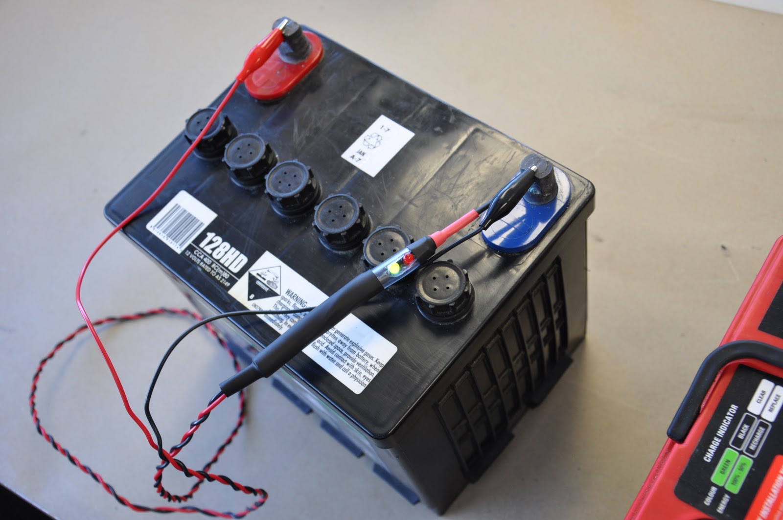
both Red and Green LEDs should light up when connected. as per diagram, current flows from positive to negative in circuit. both leds will receive "+" and "-" at correct polarity.
when probe (metal Rod) contacts the Battery positive it creates a new circuit where Probe becomes + and current flows from probe Positive to negative through Red LED. Green LED will receive positive at both terminals (anode and cathode)
Red LED will become brighter once contacts Battery positive. Current flow would go from Positive Probe to negative through Red LED and Resistor (R2) avoiding Green LED's Resistor (R1).


No comments:
Post a Comment