Thursday, 13 October 2011

Resistors


Resistors


linear resistor is a linear, passive two-terminal electrical component that implements electrical resistance as a circuit element. The current through a resistor is in direct proportion to the voltage across the resistor's terminals. Thus, the ratio of the voltage applied across a resistor's terminals to the intensity of current through the circuit is called resistance. This relation is represented by Ohm's law:
I = {V \over R}     (sorce: Wikipedia)


Axial-lead resistors (left side) and power resistors (right side)


Resistor Colour-code:


Electronic Symbol:

Testing:
Resistor can be tested with ohmmeter by connecting two terminals to the meter.


Potentiometers

Potentiometer is 3 terminal resistor with sliding wiper that forms an adjustable voltage divider. Potentiometer can be easily turned in to rheostat (or variable resistor) by using just 2 terminals: one side of the resistor and wiper. Applications: volume control in sterio systems, some car sensors (TPS, AFM). 
In time potentiometers wear out and become noisy. 

Electronic symbol: 


Wednesday, 12 October 2011

Oxygen Sensors


Oxygen Sensors

Oxygen Sensor is a feedback sensor that tells ECU if there is oxygen in exhaust gas, so ECU can adjust the mixture close to Lambda 1 (14.7:1). Oxygen Sensor is passive sensor which does not require power to run, it outputs its own voltage. Purpose of the sensor is to protect the CAT.
Ledded fuel will destroy O2 Sensor as well as some silicone gasket makers.
In time O2 sensors become "lazy" they become less responsive and don't switch voltage as fast as needed. It's recommended to change them every 60 000 km or whenever engine light comes on.

O2 is similar 1V Battery. depending on amount of oxygen in exhaust gas it outputs a range of voltages from 0V to 1V. So the leaner the mixture the closer to 0V:


0V is lean
0.45V is ideal
0.9V is rich


Bosch O2 sensor wires colour code:
1 wire: Signal (black)
2 wire: signal (black) and earth(grey)
3 wire: heater wires (white) and signal (black)
4 wire: heater wires (white), signal (black) and earth (grey)

3 types:
Zicronia
Titania
Wideband

upstream and downstream (before and after CAT)

most new cars have 2 Before and after CaT to see if CaT working

V engines got O2 sensor per bank, so most of V12 got 4 O2 sensors

need to be at 500-600 degrees to operate properly


Wideband:

1 cell: 4 wires
2 cell: 5-7 Wires

tells how rich the mix is


Thursday, 6 October 2011

Fuel Injections - air flow meters

There are a few different types of how air flow getting represented to ECU.
Directly:    K-Jetronic - Mechanical
                 L-Jetronic - Flap (or Vane) controlled. air flow pushes the flap inside the airflow meter box and wider the flap opens it means more air pushing it, so it would need more fuel for Lambda one. Disadvantages: spring on the flap becomes loose, restricts air. most early European cars, early Toyotas have it. there are two types of Flap Air meters: the ones that output around +4.5 V when idle and ones that output close to 0 when idle. this one is from Toyota MR2 and it outputs around +4.5V when flap is fully closed (at idle).


Testing:

according toyota manual there are 4 terminals: VC (+5V in), E2 (earth), VS (sensor output) and THA (temperature sensor)


       check the resistance according the manual.
wire the AFM up to 5V power supply and check the output voltage.
        

the voltage goes down as flap opens

checking it with scope


H-Jetronic - Hot Wire. The air flow sensor has got a titanium wire inside.Titanium wire gets hot when ECU puts current through it and changes it's resistance
Indirectly:  D-Jetronic - Map Sensor. Measures pressure in plenum chamber.

Monday, 12 September 2011

Injector Circuit

For this assignment we were given this diagram 


according Motorola Datasheet current gain on BC547 transistors is 110 to 800
Voltage = 12V
choosing proper resistors for LEDs:
ILED = 30mA
VLED = 1.8V

RLED = (VSupply - VLED) / ILED

RLED = (12-1.8)/0.03= 340 Ohms
So I would use two 330R resistors for R14 and R15

β=Ic/Ib
Ib=Ic/β
Ib=30/110=0.27mA

R=(5V-0.7V)/0.00023A=18695.65 Ohms

so I choose to use 15K resistors for R13 and R16

Parts List:
BC547 transistor x 2
Green LED x 1
Red LED x 1
330R resistor x 2
15K resistor x 2
PC board 

Lochmaster Diagram


Video


Monday, 29 August 2011

O2 sensor Tester

Calculations:

R5
V=12V-9V=3V
I=5.6mA

V=IR
R=V/R
R5=3/0.0056=535.7 Ohms

====================================================================

Vtotal = 9V
V(R7)=0.23V
V(R8)=0.63V-0.23V=0.4V
V(R6)=9V - 0.63V = 8.37V
R6= 10 000 Ohms

I=V/R
I = 8.37/10 000 = 0.000837A =0.837mA

R8 = 0.4/0.000837= 477.9 Ohms
R7 = 0.23/0.000837 = 274.8 Ohms

====================================================================

R = (Vs-Vled)/Iled

R2 = (12-1.8)/0.0095= 1073.7 Ohms
R3/4 = (12-1.8-0.7)/0.0095 = 1000


=====================================================================


Part list:

3 x Diodes 1N4001
3 x Resistors 1K
1 x Zener Diode 9V1
1 x 3mm Green LED
1 x 3mm Yellow LED
1 x 3mm Red LED
2 x Capacitors 0.1uF
1 x Resistor 10K
1 x Resistor 270R
1 x Resistor 470R
1 x Resistor 540R
1 x IC LM324AM


====================================================================


Lochmaster Diagram:


top side:


Bottom Side:


Video:


Thursday, 4 August 2011

Checking Alternators

On car check


Checking alternator on 1991 Toyota MR2. Make sure that the vehicle is in neutral (or park) and hand brake is applied firmly.
Check list:
  1. Does Charge light work?  Yes
  2. Visual condition of the connectors. OK
  3. Alternator mounting. OK
  4. Fuses and fusible links. OK
  5. Condition of the drive belt (tension, cracks or rips). OK
Tools required: Hight rate discharge tester, multimeter, clamp amp meter.

No load test.
Battery OCV (Open Circuit Voltage) - 12.67V
for this test all doors need to be closed, all lights switched off and ignition key is out. Alternatively, Battery negative terminal can be disconnected. Using digital multimeter measure voltage of the battery.

Specified Regulator voltage - 14.9V 
voltage is found in service manual for the car. acceptable voltage is 13.5V to 15V


Regulator Voltage Reading - 14.89V
start the car. measure the voltage at the battery while engine is running.

No load Current output - 15A @14.7V
Clamp Amp Meter required for this test. place clamp over negative/positive battery terminal. readings for carburettered car should be 5A to 12A and for fuel injected - 10A to 18A.


Current output under the load - 80A@13.4V
High Rate Discharge Tester is required for this task. Dial 50 Amps on the Tester, start the engine and connect the tester terminals to the battery. Rev the car up to 2000 RPM and turn the tester ON for no more than 20seconds. Take the readings from Load Tester.


The Alternator has Passed all tests and it is fully functional.


OFF Car Check


Visual inspection: check the alternator for any Damage to back cover, bearings, terminals...


Disassembly:

<!--[if !supportLists]-->1.        <!--[endif]-->Unscrew the nut on “B+” terminal and insulator.

<!--[if !supportLists]-->2.        <!--[endif]-->Remove three nuts holding the back cover and take it off


3.        Remove the brush holder and voltage regulator.

4.        Remove the four screws that hold the rectifier, remove the rectifier.

5.        Remove the four screws that hold the voltage regulator, remove the regulator.


Monday, 16 May 2011

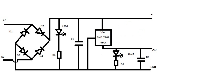
5 Volt Regulator/rectifier

For this assignment we have been given out the following parts:
4 x Diodes 1N4001
2 x Capacitors 100 uF
1 x Red LED
1 x Green LED
1 x Voltage regulator TS7805
2 x 1K Resistors
1 x Circuit board
different colored wires


The circuit diagram (updated)


Lochmaster printout


AC voltage coming from Neutral (N) and Phase (P) connectors is getting rectified by four diodes to DC voltage. then Red LED lights up indicating that rectifier works correctly. Green LED after voltage regulator indicates that voltage is 5V after regulator.


testing:
supplying 12V DC after rectifier, both LED lights should light up


Supplying AC Voltage to the rectifier


Red wire reads 17.35V DC


the white wire reads 4.9V DC